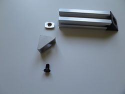
Parts for this section
A simple and very useful upgrade for any 3D printer is a good quality filament spool holder. Although several spool holders are available, some of them require more "pulling" efforts from the extruder motor. In some cases the extruder pulls the filament spool which completes a partial rotation providing some slack to the extruder only to have the extruder having to increase the force on the spool once again. Since the extruder motor deploys a constant force, the resulting change in required force has the effect of causing noticeable uneveness in prints. This low friction, smooth rolling filament spool holders eliminates this problem.
Key features:
-
Extremly smooth rolling motion requiring minimal pulling effort from extruder motor
-
Fits almost any size filament spool
-
Can be mounted anywhere on the V-Slot linear rails
Lautr3k
- Spool Holder -
UPGRADE

Assembly


-
Plastic parts:
-
2x Spool Centers
-
608 washer
-
Clip
-
-
2x V-Slot Linear Rail 20 x 20 profile x 250mm
-
V-Slot Linear Rail 20 x 20 profile x 100mm
-
3x Black Angle Connor Connector (20mm x 20mm backet)
-
4x Silver Cast Corner Bracket (20mm x 20mm bracket)
-
10x M5 x 8mm screws
-
2x 608zz bearings
-
6x T-nuts
-
4x Drop-in T-nuts
-
Washer (inner diameter 3/8")
-
Threaded rod 3/8" diameter x 20mm
Take one of the 250mm V-Slot Linear Rails and insert a T-Nut at one end.
Slide the T-Nut in the chanel along the rail and place a Black Angle Corner Connector on top of the T-Nut.
Insert an M5 x 8mm screw through the Black Angle Corner Connector to the T-Nut and tighten the screw to fasten the Black Angle Corner Connector in place. This connector will eventually support the rod which holds the filament spool.
In the other end the V-Slot Linear Rail, slide the T-Nut in the chanel and keep it near the edge..
Place a sliver Cast Corner Bracket on top of the T-Nut, and align the hole in the bracket with the screw hole in the T-Nut. Insert an M5 x 8mm screw and fasten to lock firmly in place.
On the opposit side of the silver Cast Corner Backet, insert an M5 x 8mm screw through the hole and lightly screw-in a Drop-in T-Nut.
Once the Drop-in T-Nut is attached it looks like this. The Tower Assebly is complete.
Repeat this section with the second 250mm V-Slot Linear Rail to build the second Tower Assembly.
Take the 10mm V-slot linear rail, one Black Angle Corner Connector and one M5 x 8mm screw.
Using a tap to thread a hole for an M5 screw or 10-32 screw or #10 screw, thread the hole at the center of the end of the V-slot linear rail.
Insert the M5 8mm screw into the hole that you just tapped and fasted the Black Angle Corner Connector.
Next, slide a T-Nut in the V-Slot Linear rail and keep it near the edge. Take a Silver Cast Corner Bracket and insert an M5 x 8mm screw. Fasten the bracket firmly.
Take a Drop-in T-Nut and another M5 x 8mm screw. Insert the screw into the remaining hole in the bracked so the foot comes through and then screw in the Drop-in T-Nut very losely.
Repeat the last two steps using another Drop-in T-Nut and another M5 x 8mm screw. This is what it looks like once the Guide Assembly is complete.
For the final phase you'll need the M8 nut, an M8 washer, 2 x 608zz bearings, the plastic "washer", "clip", "spool holder", and the 5/16" x 200mm threaded rod.
Insert one 608zz bearing in each of the opening plastic "spool holders".
Insert the threaded rod through the spool holder assembly, then place the washer against the bearing side of the spool holder. Finally screw in the nut on the threaded rod.
Place the rod and spool holder assembly through one side of the filament spool, and then place the second spool holder on the rod from the opposit side to sandwich the filament spool in bewteen. Once in place, slip on the plastic washer and fasten in place with the plastic "clip".
Force the Drop-in T-Nut from one of the tower assemblies into the 3D printer's V-Slot Linear Rail. Then tighten the M5 x 8mm screw to secure the first tower in place. Repeat with the second tower assembly making sure that you face the Black Angle Corner Connectors towards the middle as shown.
You can now place the each end of the rod in the Black Angle Corner Connectors on each tower.
Finally, force the two Drop-in T-Nuts on the Guide assembly into the same cross-bar that the two Tower assemblies are fastned to. Tighten the two M5 x 8mm screws holding those Drop-in T-Nuts to lock the Guide assembly in place.
When threading the filament to the extruder make sure the pass the filament through the opening in the Black Angle Corner Connector as shown.
Happy printing !

